Continuing in our Drafting series, we’ve already built the theater, hung and focussed the lights, set the booms. It’s important to note that Capture reverses the process you may be used to from Vectorworks- draw something in 2D and adjust it into 3D when you do your visualization. In Capture, you start in 3D and vis and finish in 2D, editing a plot out of your existing design. So let’s dive into making the plot look good and easy to read. A last heads up- Capture 2021 revised this process a bit, so there will be new windows and options in this tutorial. Open your existing file of the Aerial show we’ve been working on, and let’s get started.
It’s a good idea to keep your plot adjustments in their own layer, so go to Design>Layers and add a Layer name Plot Adjustments. Double click to the left of the label to select that layer for the things we will be adding.
Next we will reconfigure the booms so they can be clearly visible on the plot. In my experience, I’ve found it is very easy to move lights for the plot (while keeping them in their original place in 3D) and impossible to rotate and move the boom pipe itself. So let’s start by going to Library>Objects>Forms and dragging out a Cylinder into your Alpha view and place it offstage of 1 Boom SR. Go to Design>Selected items and adjust the Start and End diameter of the cylinder to be 2” and make the pipe 12’ long. Go to your Beta view and use the cone to rotate the cylinder so it lays flat in the Alpha view. Then rotate the cylinder in your Alpha view so it lies Onstage/Offstage.
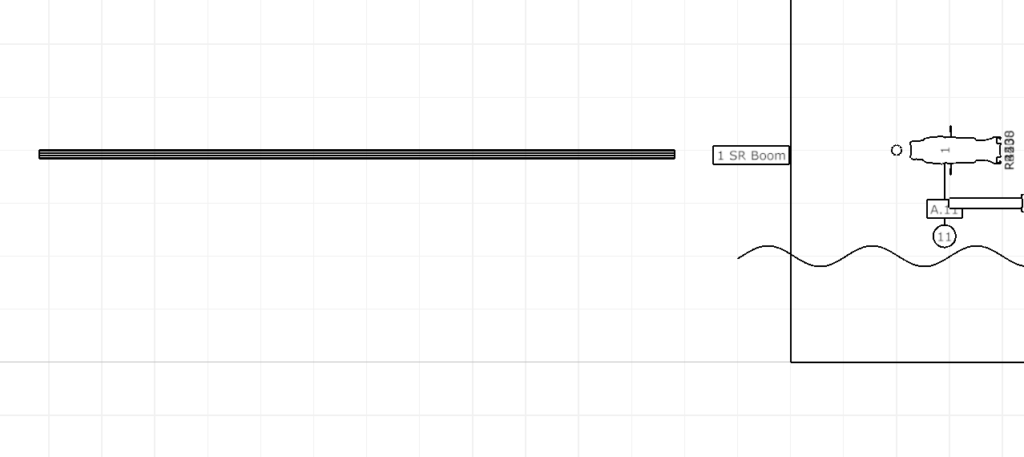
For convenience of the crew, let’s add some way to see the heights of the fixtures. Go to Library>Built in and drag a Ruler item to sit below the boom pipe. Make it 12’ long and adjust the ruler so it is in line with the boom. In Selected items, you will find an item named Segment length. Currently, it is set to one meter. Let’s set it to 6” (though you might find 12” more readable, so feel free to adjust) and then make the Alignment Right (which will place zero at the base of the pipe.)
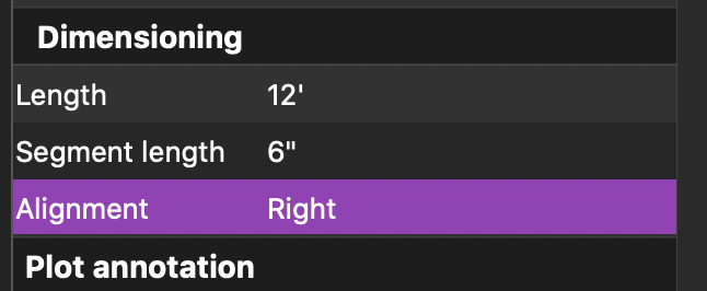
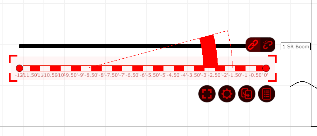
Because we have oriented the new draft version of the pipe Onstage Offstage, we will want the lights to point upstage. Select all the fixtures on the first boom in your Alpha view by drawing a tiny box over them. IMPORTANT: next, click the broken link above them to separate the changes you make now from the 3D portion of your project.
Now that you’ve double checked that your broken link is making your work safe, go ahead and rotate all the lights 90 degrees (remember- rotation will snap when you hold down Shift at the same time) to face upstage. A small frustration is the channel and address will rotate along with the fixture. So keep your selection and choose Edit>Select only>Annotations to select just the annotations. Rotate the annotations so they are below the lights again.
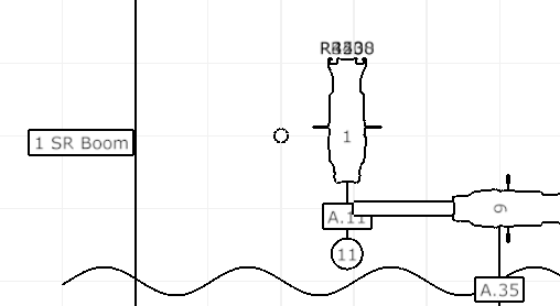
Now, one at a time, drag your fixtures over onto the 2D representation of the pipe. Measurements are:
- 11’ 6”
- 10’
- 6’ 6”
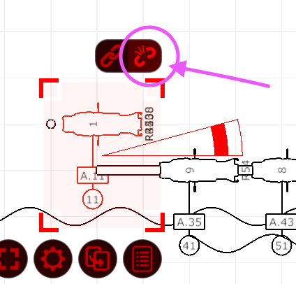
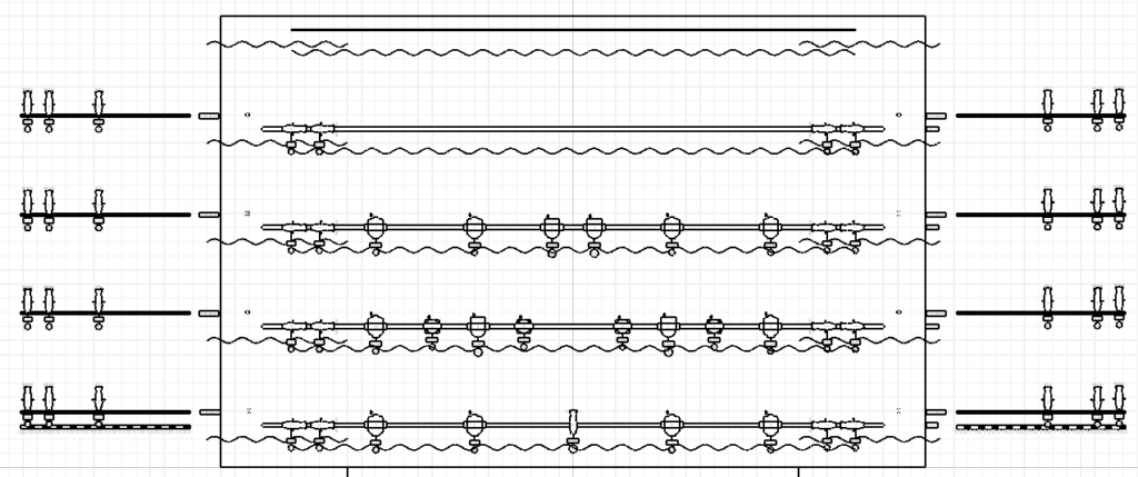
Your end result should look like this.
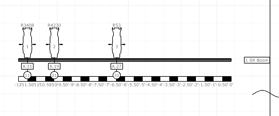
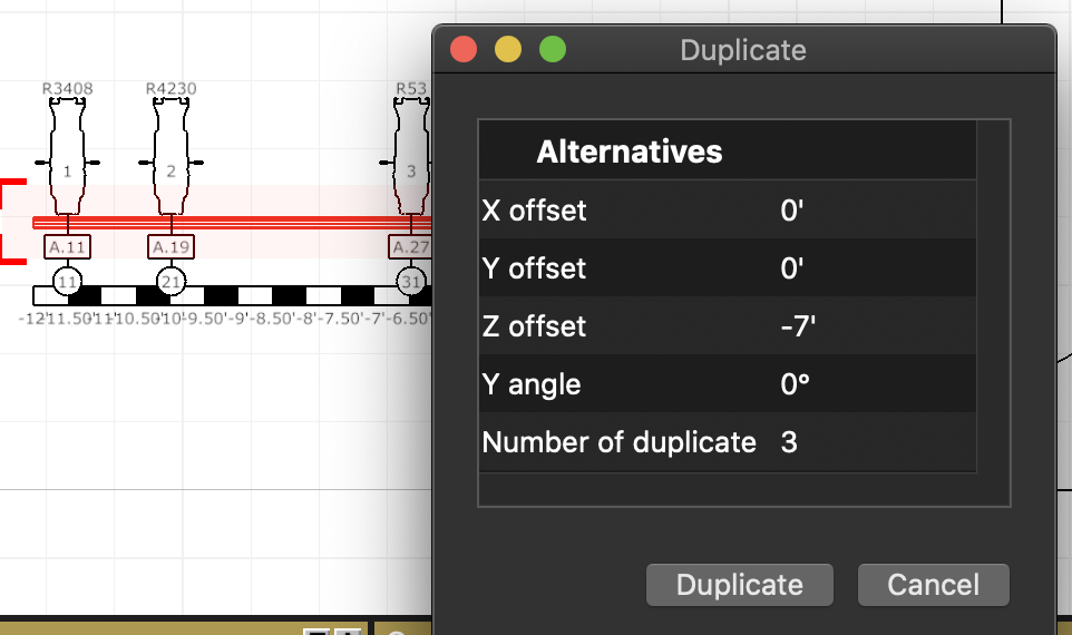
We want to duplicate the cylinder pipe to the three wings upstage. Select just the cylinder and go to Duplicate.
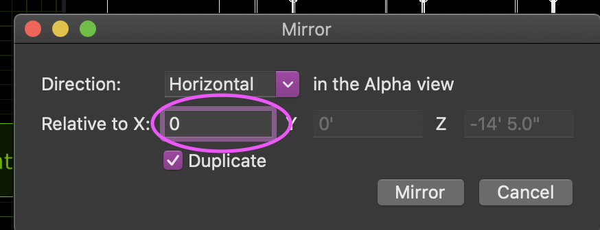
Reselect your first boom cylinder while keeping the other pipes selected as well by holding Shift and clicking the first cylinder. Go to Cog>Mirror. Set your Relative to X to zero, make sure Duplicate is checked and Press Mirror to confirm.
You now have all of your pipes SL. You cannot Mirror the ruler (which is why I didn’t have you select it), so create another ruler with the same settings on the 1 Boom SL. Now go through and place all the fixtures on the cylinder booms (making sure your Broken link is still active). I would suggest selecting all the fixture remaining on each side to rotate and adjust the annotations to save time. You should end with something like this:
It’s worth taking a moment to select any boom light to notice that a greyed-out outlined of the light will appear that shows where the light is in the 3D space. This is the neatest part of the software- the ability to set a location in 3D and a different location in 2D.
Now it’s time to set up the page size and start laying out our components. Go to Design>Plots and click the plus at the bottom of the window. Label the plot whatever you like. I’m naming it Overhead. Click Edit in the lower right hand corner. Click Paper Setup in the new window and set the paper to 24” x 24”.
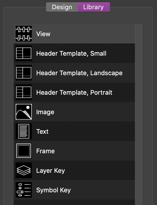
Click on the Library tab in this view (not the usual Library tab). This is where you will find everything you can add to the page.
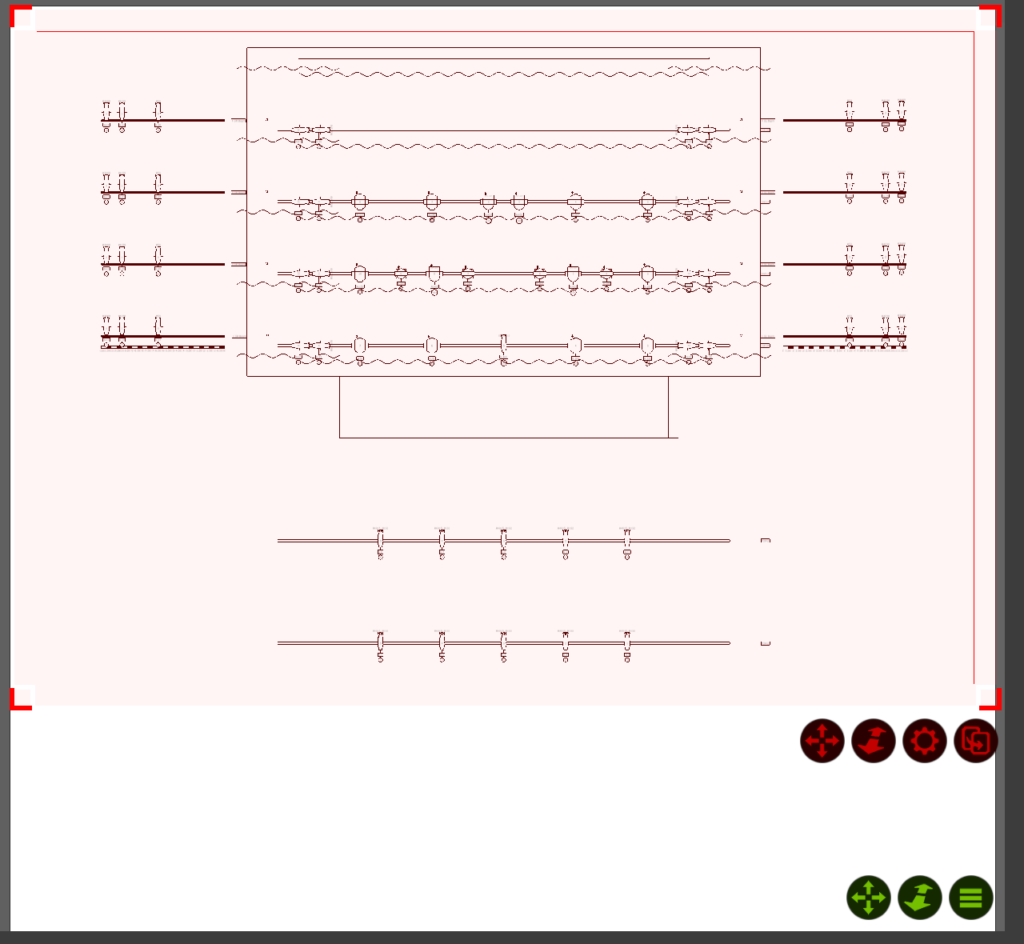
Click on the View item at top and drag it onto your page. You will notice the image is uselessly small. You will need to stretch the image by clicking on the red corners one at a time to fill the space. Confusingly, the scale is automatically tied to the size of the View box. It therefor takes several attempts to get the view and scale settled. When you have the image set to fill most of the page, click on Design tab (again- in this window!) and find the Scale value and double click it to enter 1:48 for 1/4” scale. Spend some time fussing this so it looks right. When done with this part, it should look something like this:
You may notice there is a thin border surrounding your View. I dislike this, so under Design>Border size, double click to set that to zero.
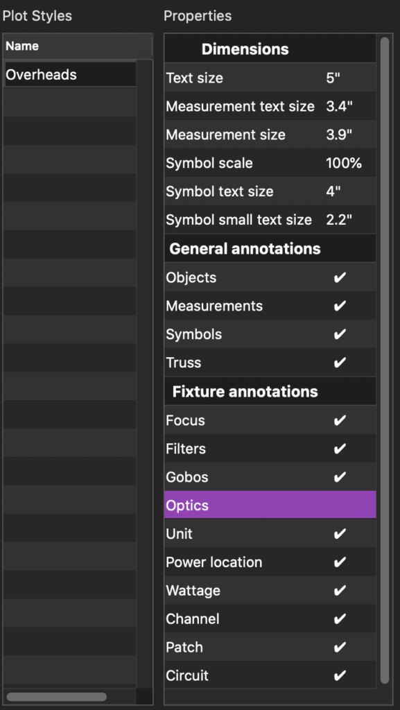
Perhaps because I’m not as young as I once was, I find the text a bit small in the default. To change this, we want to make a Plot Style. Close the Page Edit view and go to Design>Plot Styles and click the + in the lower corner to create a new style. I’m naming it Overhead as well. Change the items to match these settings, but take a moment to explore all the options. Note- you won’t see the changes unless you drag and drop the Plot Style item onto you Alpha/Plot view.
Go back to Design>Plot and click on Edit to view you page. Under Design>Plot Style, double click to select Overheads for your Plot Style and notice the change on your page view. Notice you can also select a Filter here. I recently used this to omit so architectural elements that were muddying my plot.
In your page window, go to Library>Frame and drag one to the upper left hand corner of your plot. There is a snapping behavior that may help you here. Now grab the lower right hand corner and drag out the frame until the snapping behavior indicates you are evenly around the page. Click back to design in your page view and increase your Border size to 5pt. Your Corner Radius will round the corners if you wish.
Go back to Library>Symbol Key. Drag one out to the lower left hand corner of the plot until the snapping behavior grabs the key. Stretch out the key to halfway across the page, when the snapping behavior will bring it to center and release.
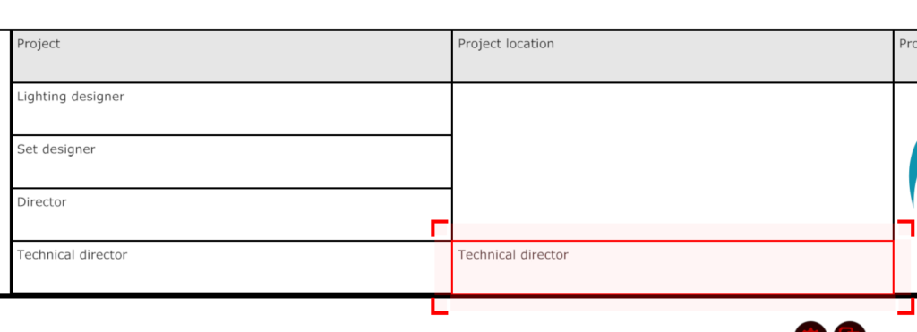
Go to Library>Header Template, Landscape and drag this out to be on the opposite side of the symbol key. All the fields here will be populated with the information you enter in Design>Project. The thing I find odd coming from other drafting applications is there is no field here to indicate scale. I typically deselect the header and select the Technical Director field, copy it and place it to the right.
Click back on the page Design tab and you will notice you can edit the information here. Double click to the right of Text and type in Scale 1/4” = 1’. Click okay. Double click below to increase the test size to 16pt.
The Capture images on the Header are placeholders you are meant to replace with whatever image your prefer. Show image, your design firm image, whatever is appropriate. You can change the image by selecting the one you want to change and under Design>Image, double click on the image and select one you prefer.
One of the things I really like to do is have the mode of fixtures on the plot. It saves time with your Electricians/Shop Prep people and Programmer. You can edit what information the Symbol Key shows by selecting it and going to Design>Symbol Configuration and double clicking on the two dots to the right. From the pulldown menus that are available for each fixture type, use the pull down menu on the Quantum Profiles and select Custom Text with Count.
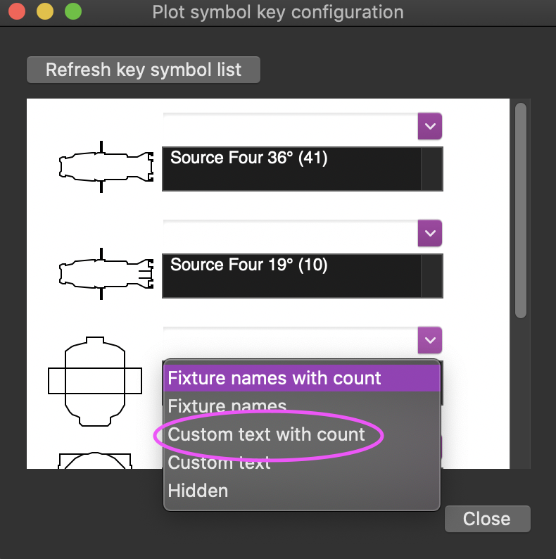
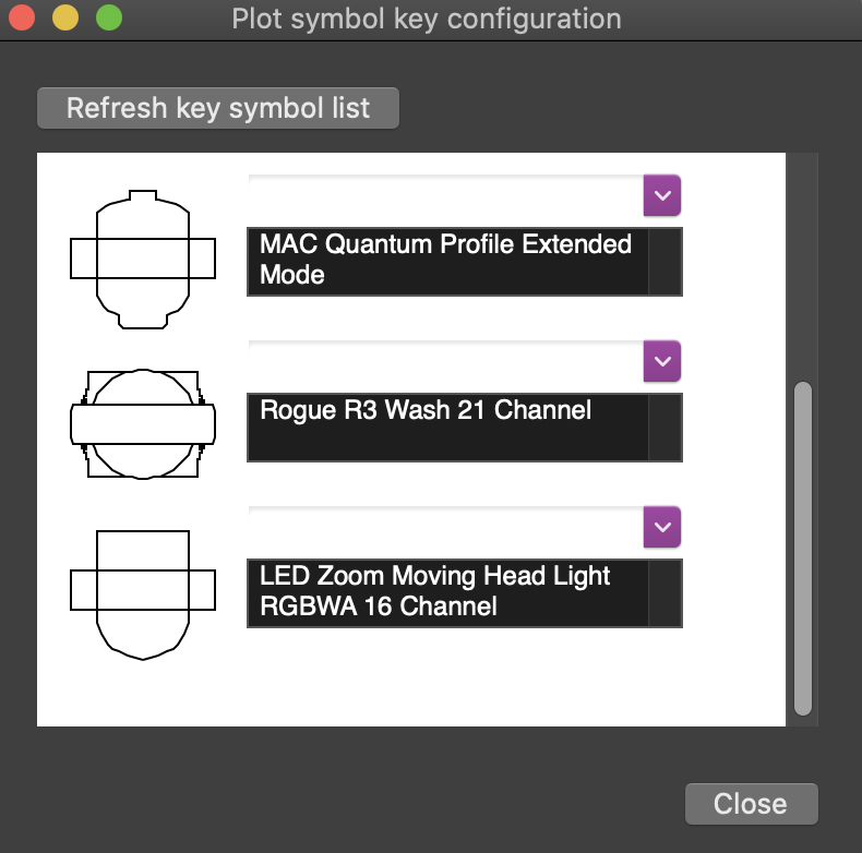
Click to the right of where it says MAC Quantum Profile in the black field and add Extended mode after the fixture name. Under Rogue R3 wash, again select Custom Text with Count and click at the end of the label to add 21 Channel. Though there is only one mode for the LED zoom moving head, omitting information sometimes confuses people. Choose Custom Text with Count again and enter 16 Channel. Press Close to confirm.
Last thing is to add the Notes. Library>Text. Drag out a Text item. I have a series of notes I add to this plot which would be meaningless for you to copy, so input anything you wish. I added mine to the lower left above the symbol key. I prefer mine inset from the frame to draw the eye.
For a basic plot- that’s it. You can, of course, add many more details, but I believe most tools you will need have already been covered in this tutorial. Check back next week when we step through the new Reporting functions to get some paperwork done. If you have questions or requests, or favorite tricks to draft better in Capture, hit me in the comments.
3 comments